
100 MHz In The Loop
Project description
General
Figure 1 shows a picture of the 100MHzInTheLoop PCB.
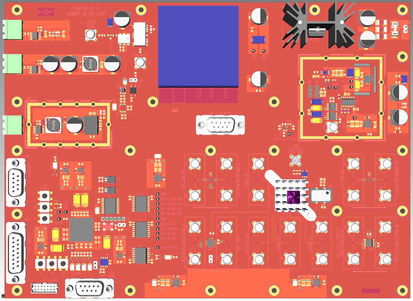
Figure 1: Preliminary Picture of the 100MHzInTheLoop PCB V3.0
Figure 2 shows a block diagram of the 100MHzInTheLoop V3.0 board (same as V2.0).
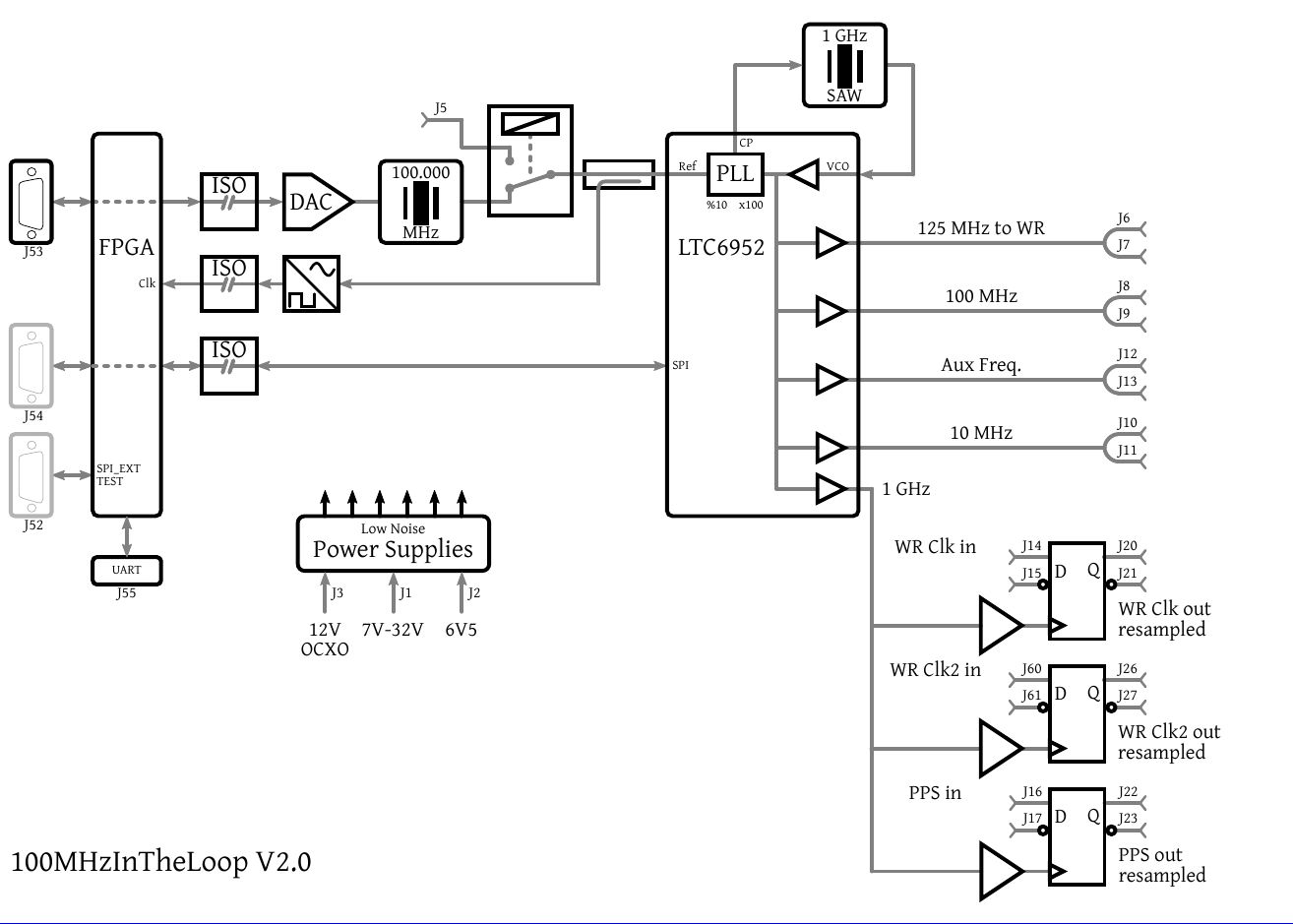
Figure 2: A Block diagram of the 100MHzInTheLoop V3.0 board (same as V2.0)
This Board contains a 100 MHz high precision low phase noise OCXO (KVG O-40B4085H-P3). The oscillator can be used as an external high precision oscillator for White Rabbit (WR) applications that need to generate low phase noise clocks.
The OCXO can be tuned via a DAC. The 100 MHz output of the oscillator is the reference for a PLL (LTC6952) that has a low phase noise 1 GHz Surface Wave Acoustic (SAW) VCO.
The PLL needs initialization via SPI. Therefore the SPI bus is connected to a Spartan-7 FPGA such that the firmware implementation of this FPGA can either feed forward an external SPI bus or drive the SPI bus stand alone via a MicroBlaze implementation.
The PLL generates a 125 MHz clock that is used as WR reference clock. It can also generate 10 and 100 MHz clock that are used in the Virgo demonstrator and ET-Pathfinder. An auxiliary frequency can be generated as well.
Lock-Sweep
In the current WR implementation (wr-cores v4.2) it is not possible to phase align the 100 MHz OCXO with the WR master. The WR phase aligned clock exists in the WR FPGA implementation and can have 5 arbitrary phase offsets w.r.t. the 100 MHz OCXO. "Lock-Sweep" is demonstrated and enables the external high precision OCXO to be phase aligned with the WR master. However, implementing "Lock-Sweep" has two drawbacks. First, the lock time (few minutes) can considerably increase since multiple attempts may be needed to get Wr in TRACK_PHASE at the proper 100MHz phase position. The latter is done by the "Tom's Casino" method by adding an extra "SYNC_LOCK_SWEEP" in the PPSi state machine (See ppsi.git). Second, currently the implementation is hacked into the software and is far from what is considered "Standard WR".
Therefor Lock-Sweep is not used and the 10, 100 MHz and PPS signals are generated by the WR implementation. The phase noise quality of these signals is enhanced by re-clocking them with a clean 1 GHz signal from the PLL.
Design details
- Schematics (Note: Design created with Mentor Graphics using a Xpedition).
- Manufacturing files 11500.04.02 100MHzInTheLoop V3.0 (Note: Design created with Mentor Graphics using a Xpedition).
- Repository containing firmware/software implementation for Spartan-7 MicroBlaze"
Older versions and relevant information
- 100MHzInTheLoop_V1.0
- 100MHzInTheLoop_V2.0
- Increase DAC granularity; piggyback DAC20
Contacts
General questions about project
- Guido Visser -Nikhef
- Peter Jansweijer - Nikhef
Status
| Date | Event |
|---|---|
| 29-09-2020 | Initial Meeting with LAPP. |
| 17-03-2021 | Start working on project. Collecting main specifications. |
| 15-10-2021 | 100 MHz In The Loop ready for production. |
| 15-11-2021 | After survey of quotes; 4 boards ordered. |
| 07-02-2022 | 4 boards received. |
| 23-02-2022 | 100MHzInTheLoop operational with SPEC7 + FMCBreakout_extended. |
| 05-10-2023 | Updated with 100HzInTheLoop V2.0. |
| 28-11-2023 | Added DAC20 info |
| 15-01-2024 | Added 100MHzInTheLoop V3.0 |
| 14-02-2024 | First prototype of 100MHzInTheLoop V3.0 arrived and is functional |
23 February 2024

