Different multiplexer strategies resource utilization
Introduction
In felix we use many multiplexers to concentrate data inside the FPGA. In the code different mux coding stiles have been used. The purpose of this study is to determine whether one VHDL representation results in a more efficient logic representation than the other.
Toplevel
At toplevel for this investigation, a top vhdl file instantiates 4 different multiplexers with the same behaviour, and the same port map. Only the generic muxtype determines the internal 8:1 mux being used. This mux is used in Felix at multiple places in the Central Router.
entity MUX8_16bit_sync is
Generic(
    muxtype: integer := 0
    );
Port (
    clk      : in  std_logic;
    data_rdy : in  std_logic_vector(7 downto 0);
    data0    : in  std_logic_vector(15 downto 0);
    data1    : in  std_logic_vector(15 downto 0);
    data2    : in  std_logic_vector(15 downto 0);
    data3    : in  std_logic_vector(15 downto 0);
    data4    : in  std_logic_vector(15 downto 0);
    data5    : in  std_logic_vector(15 downto 0);
    data6    : in  std_logic_vector(15 downto 0);
    data7    : in  std_logic_vector(15 downto 0);
    ---------
    sel      : in  std_logic_vector(2 downto 0);
    ---------
    data_out : out std_logic_vector(15 downto 0);
    data_out_rdy : out std_logic
    );
end MUX8_16bit_sync;
Mux instantiations
MUX0: parallel clocked mux
This is the most simple mux that consists of one clocked process that multiplexes the selected 16 bit dataword depending on sel[2:0]. This is also the implementation currently used in Felix.
mux8x: process(clk)
begin
    if clk'event and clk = '1' then
        case sel is
            when "000" => data_out_p1_s <= data0;
            when "001" => data_out_p1_s <= data1;
            when "010" => data_out_p1_s <= data2;
            when "011" => data_out_p1_s <= data3;
            when "100" => data_out_p1_s <= data4;
            when "101" => data_out_p1_s <= data5;
            when "110" => data_out_p1_s <= data6;
            when "111" => data_out_p1_s <= data7;
            when others =>
        end case;
    end if;
end process;
MUX1, MUX2 and MUX3, different behavioral instantiations of a 1-bit 8:1 mux, inside a for-generate mux.
The code 1-bit MUX is instantiated as follows, in order to represent the same as last paragraph a pipelining stage is added.
g_mux16x8: for i in 0 to 15 generate
begin
    mux: entity work.MUX8(behavioral1)
    port map (
        sel    => sel,
        data0   => data0(i),
        data1   => data1(i),
        data2   => data2(i),
        data3   => data3(i),
        data4   => data4(i),
        data5   => data5(i),
        data6   => data6(i),
        data7   => data7(i),
        data_out => data_out_p0_s(i)
    );
end generate;

process(clk)
begin
    if clk'event and clk = '1' then
       data_out_p1_s   <= data_out_p0_s;
    end if;
end process;
The different architectures of MUX8 are given here:
behavioral in a process
architecture behavioral1 of MUX8 is
begin

process(data0,data1,data2,data3,data4,data5,data6,data7,sel)
begin

    case sel is
        when "000" => data_out <= data0;
        when "001" => data_out <= data1;
        when "010" => data_out <= data2;
        when "011" => data_out <= data3;
        when "100" => data_out <= data4;
        when "101" => data_out <= data5;
        when "110" => data_out <= data6;
        when "111" => data_out <= data7;
        when others =>
    end case;

end process;

end behavioral1;
behavioral using with select
architecture behavioral2 of MUX8 is
begin
  with sel select
    data_out <= data0 when "000",
                data1 when "001",
                data2 when "010",
                data3 when "011",
                data4 when "100",
                data5 when "101",
                data6 when "110",
                data7 when others;
end behavioral2;
low_level MUX8
architecture low_level_MUX8 of MUX8 is

signal lut0_out, lut1_out : std_logic;

begin

---------------
lut0_inst: LUT6
generic map (INIT => X"FF00F0F0CCCCAAAA")
port map(
    I0 => data0,
    I1 => data1,
    I2 => data2,
    I3 => data3,
    I4 => sel(0),
    I5 => sel(1),
    O  => lut0_out
    );
---------------
lut1_inst: LUT6
generic map (INIT => X"FF00F0F0CCCCAAAA")
port map(
    I0 => data4,
    I1 => data5,
    I2 => data6,
    I3 => data7,
    I4 => sel(0),
    I5 => sel(1),
    O  => lut1_out
    );
---------------
combiner0_muxf7: MUXF7
port map(
    I0 => lut0_out,
    I1 => lut1_out,
    S  => sel(2),
    O  => data_out
    );
---------------

end low_level_MUX8;
Conclusion
| Name | Slice LUTs | Slice Registers | F7 Muxes |
|---|---|---|---|
| Mux0: Clocked parallel process | 35 | 51 | 16 |
| Mux1: 1-bit combinatorial process | 35 | 51 | 16 |
| Mux2: 1-bit with select | 35 | 51 | 16 |
| Mux3: low level instantiation | 35 | 51 | 16 |
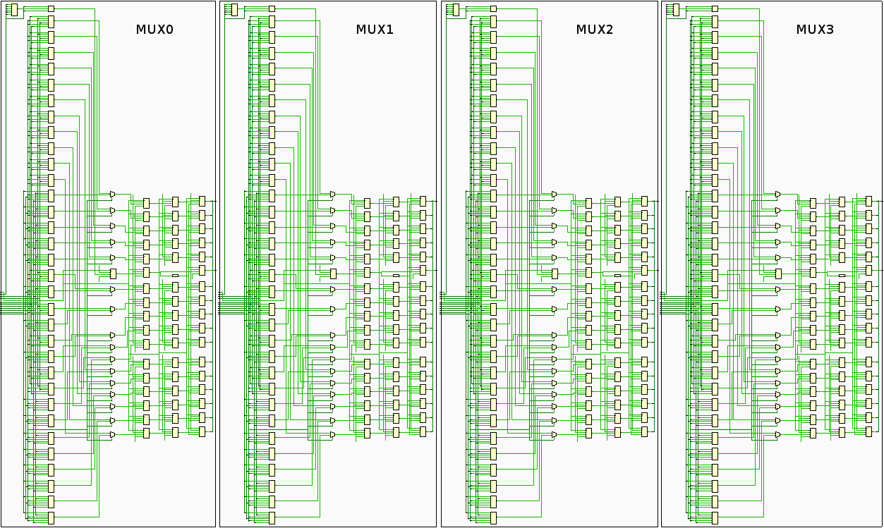
Bottom line is that independent on how you write down the 16-bit 8:1 MUX, Vivado will understand that it is a MUX and create exectly the same logic cells out of it after implementation.
Also the schematic representation of the different architectures after Vivado implementation looks exactly the same:


